Model Rocket Thrust Stand
This project is a thrust stand for an Estes A10-0T model rocket motor. I built this to see how closely a thrust curve from an at-home stand could resemble an official one from certified testers.
Setup
I used a cantilever load cell with custom 3D-printed mounting hardware, screwed into a wood base. The load cell passes analog data to an ADS1220 ADC breakout board, which communicates with an ESP32 microcontroller to stream data over Bluetooth to a client. The first two launches were recorded on an old Canon PowerShot and were time-synchronized via two quick taps. Weight calibration consisted of known weights (measured by a standard kitchen scale) of various objects, including a JBL speaker, a case of drill bits, and a ~10 lb dumbbell (that turned out to be a little over 10 lbs).

Wiring diagram
The load cell is connected to the ADS1220 breakout. Green SIG+ to AIN1 and white SIG- to AIN2. Red EXC+ connects to the 3.3 V rail and black EXC- connects to ground. REFP0 and REFN0 connect to those same rails so the ADC references the load cell excitation voltage. Communication happens over SPI; onboard circuitry is omitted from this informal schematic.
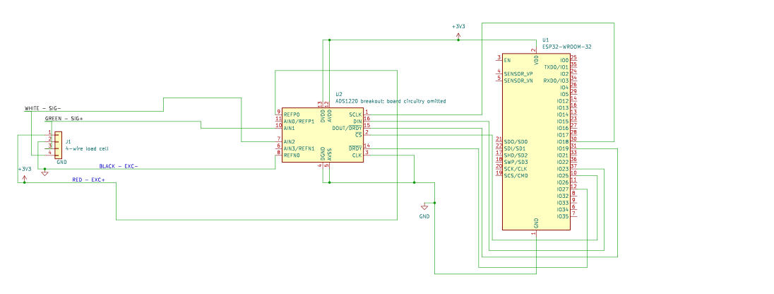
Recorded launches
All runs
Results & interpretation
Three of the four runs had a peak thrust of ~9.9 N. Launch 2, however, had a peak of about 15.1 M. Its total impulse was also higher, however this difference was far smaller than the difference in peak thrust.
| Run | Peak thrust | Impulse (over ~0.9 s) |
|---|---|---|
| 1 | 9.93 N | 1.689 Ns |
| 2 | 15.10 N | 1.860 Ns |
| 3 | 9.88 N | 1.688 Ns |
| 4 | 9.89 N | 1.676 Ns |
The average impulse was about 1.73 Ns, with about 5% variation between runs. Peak thrust had a higher variation at about 23%, mostly due to the second launch. This could be caused by variation in the stand as well as variation between motors.
The reference thrust curve also disagrees. Estes lists the A10-0T at 2.50 Ns total impulse, 13 N maximum thrust, and a 0.80-second burn time. The NAR motor list lists the A10T at 1.7 Ns. My average is close to the NAR value, yet still about 31% below the Estes value. This makes it difficult to do an anaylsis on how closely these motors matched their specifications.
Timing is also an issue. Peak thrust happens about 0.3 seconds after ignition, which is plausible, but the video shows a visible flame for about 1.67 seconds and there is still (a weaker) force being applied near the end of the burn. I don’t have an explanation for the longer flame duration.
Including the force tail until the readings return to the relative baseline raises the average impulse to ~2.15 Ns.
Sources of error
The calibration process used objects weighed on a kitchen scale, with different mounting hardware for the dumbbell (and other objects) and the motor. Something I would check is whether the calibration items applied force at the same point on the load cell. Applying the weights at different distances could add variation into the data.
Support stiffness (the wood), among other sources of error, could marginally contribute to additional variation. For example, the igniter wires may have pulled on the motor mount before they fell away as the igniter burned.
Launch 2’s peak is, again, considerably higher than the other three. I do not have an explanation for why, however the burn in the second launch appears larger than that of the first. Then again, this could be due to the low frame rate of the camera.
Next time
I would calibrate more accurately by using standardized known weights instead of using a measurement from a kitchen scale, and by designing better fitting mounting hardware. I would apply said known weights at the same distance on the load cell that the motor applies its force. A more incremental calibration process may also assist in accuracy. I would also use a stiffer mount and secure the igniter leads so they couldn’t pull on the load cell.
Overall, the stand did render fairly consistent impulse estimates with a less consistent peak. However, if the second launch is to be disregarded, the consistency improves significantly. I still need to explain the weak tail and the longer visible flame than the motor is specified before considering the stand’s produced curves as an accurate measurement of the motors thrust.